INSTRUCTIONS FOR ACCURA-FLEX (WITH QUADOMETER ATTACHMENT)
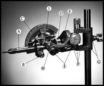
"A"
Dop reference point or radio alignment: This is a cone pointed set screw in the dop arm 1 ¼ " from the end of the
collet chuck. The purpose of this reference point is to radio align the grooved dops into a fixed position., i.e.: the groove of
the dop corresponds with the cone point when the dop is inserted into the collet chuck.
The reference point (cone pointed set screw) is properly adjusted when the grooved dop will slide easily into radio
alignment. If the set screw is adjusted in too far then it will bind in the groove of the dop.
DO NOT adjust the set screw against the groove of the dop after inserting the dop into the chuck. Before tightening the
collet chuck turn the dop against the set screw. This will remove any error between the groove of the dop and the set
screw. The gem is now cut after which the transfer set screws in the transfer block keeps the dops in proper alignment
while the transfer is accomplished. After transferring is completed, the new dop is inserted into the collet chuck so that the
groove of the dop and the cone point will correspond as previously mentioned. However, the direction that the dop must
be turned to remove error of the sliding fit must be reversed to that established before the transfer. This reversal in the
rotation of the dop is due to the fact that the relation of the gem to the reference point has been reversed throughout the
transfer sequence. I.e.: if the second dop or transfer dop must be turned against the reference point counter clockwise.
The reference point of the dop arm also allows the operator to remove and then re-insert the dop and gem during any
phase of the cutting or polishing operation.
The cone pointed set screws in the transfer block are also adjustable with the long 5/64" allen set screw wrench. These
set screws will be properly adjusted when the dop will slide within the "V" way without any rotation. Important: Do Not
adjust these set screws too high as this will tend to interfere with the parallel alignment of the dops.
"B"
Radio tooth index splitter: Knob is marked "R", "L", right and left turn calibrated with 5 degree increments.
"C"
Free wheeling pin: This pin when inserted will allow the dop arm to be turned without the trigger engaging the index
gear. This allows the operator to round or preform the gem. The pin is removed to engage the index trigger with the index
gear.
"D"
The index gear may be removed by loosening the allen set screw in the gear hub (use the
5/64" allen wrench). Note the flat on the dop arm shaft. The allen set screw of the index gear must be tightened on this
spot only.
"E"
Chrome cap nut: This nut is loosened when an adjustment of the compound angle splitter is needed. After
adjustment is accomplished re-tighten this nut.
"F"
The three set screws "F" align with the micro-height shaft parallel to the upright and lap arbor. When adjusted
properly the dop arm will swing true across the master lap.
"G"
The two jib screws and locking nuts are used for adjustment of the mast or upright bearings.
"H"
The brass thumb screw "H" allows the operator to adjust the amount of torque needed to raise or lower the dop arm.
I.e.: a brake. When adjusted properly, the brake will prevent the dop arm from falling onto the lap.
"I"
Positive angle stop: To adjust; loosen allen cap screw, set angle pointer at 45 degrees, insert 45 degree table dop
into collet chuck and lower onto master lap. Insert screw driver into split of angle stop. This will allow the angle stop to be
rotated in the desired direction. With the 45 degree table dop flat on the lap and the angle pointer at a reading of 45
degrees the stop is adjusted so that it will be against the angle pointer. Note this has been adjusted at the factory. Do
Not re-adjust unless the facet head dropped and was knocked out of alignment.
All bearings throughout the instrument are oil impregnated and have been pre-greased for lifetime wear. The only upkeep
needed is to keep the instrument clean and free from cutting debris.
"J"
Quadometer Attachment (see special instructions).
Standard friction torque drive base:
"Base" (Friction drive) The amount of pressure that the friction disc exerts upon the drive wheel is very important for
efficient running and wear. Too little pressure will cause the drive wheel to slip when working pressure is applied. Too
much pressure will cause the drive wheel to wear out rapidly. The correct pressure is just enough to prevent slippage
when a working torque is applied.
"IMPORTANT" If is becomes necessary to remove the motor and then re-install it, be sure to align the motor shaft with
the center of the lap arbor. If the motor shaft is not in line with the lap arbor; undue wear of the drive wheel will occur.
Note: Standard 5k045 AC motor: The normal running temperature is hot to the touch especially after long running
periods.
"SElectra-Matic Base with variable speed motor:"
To insure long brush life of motor, turn off motor when not cutting or polishing. Belts should have a small or slight amount
of slack. Too much slack, however, will cause slipping. Too much tension will cause an overload of the motor.
Note" This unit has two step pulleys with four steps each. This allows the operator to select a high or low mechanical
speed. The infinite selection of speed is accomplished with the electronic speed control. This unit will facilitate most
cutting and polishing when set in the low mechanical speed range. Low mechanical speed range set at the factory.
SElectra-Matic Base with AC 115W Motor:
Speed change is accomplished by step pulleys only. See notation above on belt tension. Normal motor running
temperature is hot to the touch.
No. 6895 Base:
This base is designed for bench or desk top mounting. Three mounting tables are provided. (Complete splash bowl, all
bearing arbor). Facet head platten 3/4" thick fully machined. Individual can use his own choice
of motor and
mounting.
ACCURA-FLEX (WITH QUADOMETER ATTACHMENT)


Send mail to webmaster with questions or comments about this web site. Copyright © 2006-2026 Poly-Metric Instruments, Inc. All Prices Subject To Change Without Notice.